IPKISS 涉及到连线功能的应用场景主要有两个:
1. 将器件彼此相连,构成完整的线路版图;
2. 绘制一段目标形状的波导,将其作为一个子器件添加进其他版图中。
一、版图中的连线功能
对于一个完整的线路级版图,包含了器件的摆放和器件之间的连线,它们构成了 i3.Circuit 模板中的specs属性。
而针对本文要介绍的连线功能,IPKISS 针对两类场景提供了布线方式:1.单对端口之间的连线;2.多对端口之间的连线
1. 单对端口之间的布线
IPKISS 提供的单对端口连线的方式有如下几种:
比较常用的布线类是 ConnectManhattan 和 ConnectBend
ConnectManhattan
ConnectManhattan 通过多段的 90 度弯曲波导与直波导连接两个端口,它有几个常用属性,如下:
| bend_radius | 该参数为波导的弯曲半径,用户可以根据工艺厂允许的最小弯曲半径调节该参数用于自己的设计 |
| control_points | 该参数为控制点,用户可以设置关键坐标以控制波导的走线趋势 |
| rounding_algorithm | 该参数为弯曲算法,如波导折弯处选择哪种弯曲策略,欧拉弯还是圆弧 |
| trace_template | 设置用来连线的波导的图层、形状等信息,如果用来连线的波导与被连接器件的端口的图层、形状信息不匹配时,ConnectManhattan会帮助用户添加一段过度波导 |
下面是一个例子,器件的布局和布线构成了 i3.Circuit 模板中的 specs 属性 :
from si_fab import all as pdk
from ipkiss3 import all as i3

gc = pdk.FC_TE_1550()
control_points = [(-40, 20), (0, 30), (50, 20)]
circuit = i3.Circuit(
 insts={"gc": gc, "grb1": gc, "grb2": gc},
 specs=[
     i3.Place("gc", position=(0, 0)),
     i3.Place("grb1", position=(-100, 0)),
     i3.Place("grb2", position=(+100, 0), angle=180),
     i3.ConnectManhattan(
         "grb1:out",
         "grb2:out",
         bend_radius=5,
         control_points=control_points,
         trace_template=pdk.SWG550(),
     ),
 ],
)

circuit_layout = circuit.Layout()
circuit_layout.visualize(show=True)
运行结果图如下:
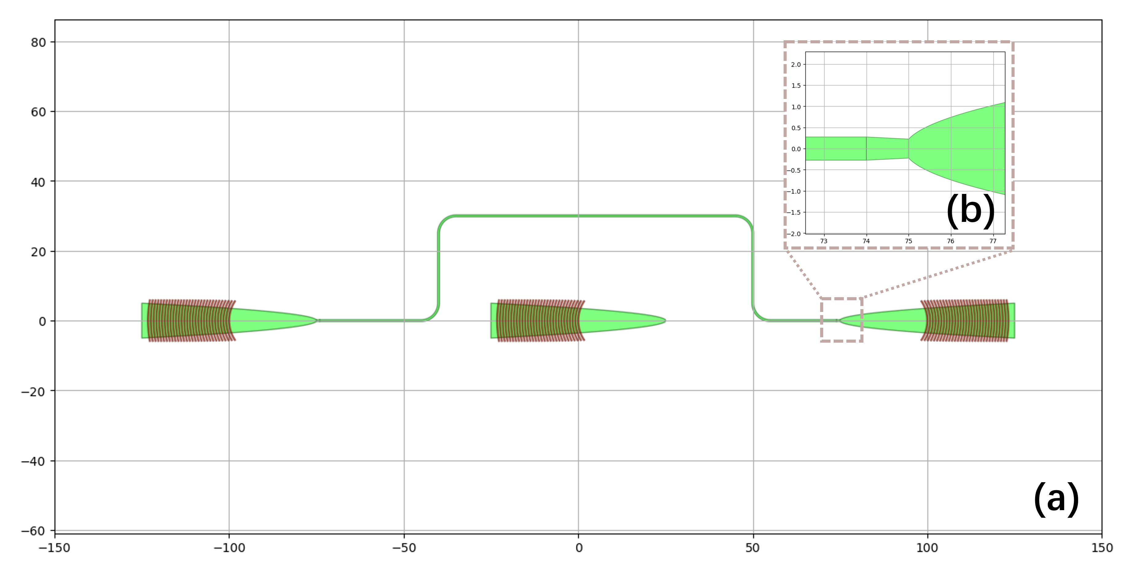
图1(a)连接器运行结果图(b)过度楔形波导
ConnectBend
用最直接的弯曲波导连接两个端口,ConnectBend 的几个重要属性如下。
注:ConnectBend 的属性不包含控制点 control_points
| bend_radius | 该参数为波导的弯曲半径,用户可以根据工艺厂允许的最小弯曲半径限制调节该参数用于自己的设计 |
| rounding_algorithm | 该参数为弯曲算法,如波导折弯处选择哪种弯曲策略,欧拉弯还是圆形弯曲 |
| trace_template | 设置用来连线的波导的图层、形状等信息,如果用来连线的波导与被连接器件的端口的图层、形状信息不匹配时,ConnectBend会帮助用户添加一段过渡波导 |
from si_fab import all as pdk
from ipkiss3 import all as i3

gc = pdk.FC_TE_1550()
circuit = i3.Circuit(
    insts={"grb1": gc, "grb2": gc},
    specs=[
        i3.Place("grb1", position=(-75, 0)),
        i3.Place("grb2", position=(+75, 50), angle=180),
        i3.ConnectBend(
            "grb1:out",
            "grb2:out",
            bend_radius=5,
            rounding_algorithm = i3.EulerRoundingAlgorithm(p=0.5),
            trace_template=pdk.SWG550(),
        ),
    ],
)

circuit_layout = circuit.Layout()
circuit_layout.visualize()
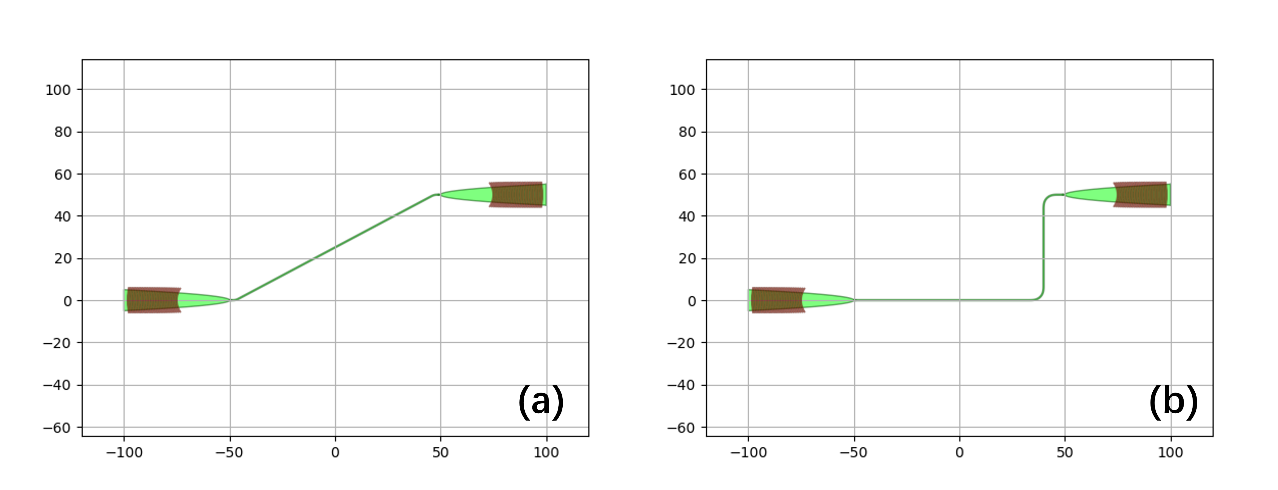
下图(a)为上述代码的运行结果图,图(b)为将 ConnectBend 连接器更换为 ConnectManhattan 的运行结果对比图
2. 多对端口之间的连接
ConnectManhattanBundle
从名字中可以看到 ConnectManhattanBundle 与 ConnectManhattan 的区别是多了一个 Bundle,Bundle 是一捆的意思,所以 ConnectMahattanBundle 的作用是连接多组端口,并且以一捆的形式。
ConnectManhattanBundle 的几个重要属性如下:
| start_fanout/end_fanout | 这两个参数分别用来设置起始端口和结束端口的扇出方式,它依赖于i3.SBendFanout,可以设置最大扇出角度等参数 |
| control_point_reference | 该参数为设置控制点control_points时的参考端口,如果不设置默认为列表里出现的第一个端口 |
| control_points | 该参数为控制点,用户可以设置关键坐标以控制“这一捆”波导的走线趋势,注意这里只能使用i3.H/i3.V的形式 |
| cover_layers | 该参数用于添加一个额外的覆盖层,用来避免可能出现的锐角DRC报错 |
| bend_radius | 该参数为波导的弯曲半径,用户可以根据工艺厂允许的最小弯曲半径调节该参数,用于自己的设计 |
| pitch | 该参数用于设置“这一捆”波导彼此的间距 |
| rounding_algorithm | 该参数为弯曲算法,如波导折弯处选择哪种弯曲策略,欧拉弯还是圆弧弯 |
下面是一个5组端口之间使用 ConnectMahattanBundle 连线的例子,代码如下:
from si_fab import all as pdk
from ipkiss3 import all as i3

fc = pdk.FC_TE_1550()
control_points = [i3.V(i3.START+100),i3.H(i3.START+100)]
circuit = i3.Circuit(
    insts={
        "fc1": fc,
        "fc2": fc,
        "fc3": fc,
        "fc4": fc,
        "fc5": fc,
        "fc6": fc,
        "fc7": fc,
        "fc8": fc,
        "fc9": fc,
        "fc10": fc,
    },
    specs=[
        i3.Place("fc1:out", (-100.0, -80.0-100), angle=0),
        i3.Place("fc2:out", (-100.0, -40.0-100), angle=0),
        i3.Place("fc3:out", (-100.0, 0.0-100), angle=0),
        i3.Place("fc4:out", (-100.0, 40.0-100), angle=0),
        i3.Place("fc5:out", (-100.0, 80.0-100), angle=0),
        i3.Place("fc6:out", (300.0 - 100.0, 300 ), angle=-90),
        i3.Place("fc7:out", (300.0 - 50.0, 300.0 ), angle=-90),
        i3.Place("fc8:out", (300.0, 300), angle=-90),
        i3.Place("fc9:out", (300.0 + 50.0, 300 ), angle=-90),
        i3.Place("fc10:out", (300.0 + 100.0, 300 ), angle=-90),

        i3.ConnectManhattanBundle(
            connections=[
                ("fc1:out", "fc10:out"),
                ("fc2:out", "fc9:out"),
                ("fc3:out", "fc8:out"),
                ("fc4:out", "fc7:out"),
                ("fc5:out", "fc6:out"),
            ],
            start_fanout=i3.SBendFanout(max_sbend_angle=80),
            end_fanout=i3.SBendFanout(max_sbend_angle=80),
            pitch=5,
            rounding_algorithm=i3.EulerRoundingAlgorithm(),
            bend_radius=20.0,
            control_point_reference="fc5:out",
            control_points=control_points,
        ),
    ],
)

circuit_lo = circuit.Layout()
circuit_lo.visualize()
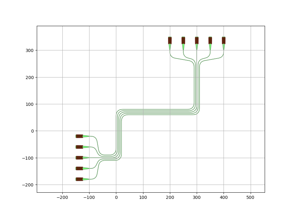
图3 ConnectManhattanBundle 运行结果图
二、绘制自定义波导,作为其他线路的子器件
有时候用户可能想自定义一段波导,并且将其作为一个模块,这样用户就可以复用这一段波导并且把它用在其他线路中。
绘制波导的方式主要有两种:
1. 输入几个关键坐标作为波导迹线
下面为一个例子
from si_fab import all as pdk
from ipkiss3 import all as i3
wg_t = pdk.SiWireWaveguideTemplate()
wg_t.Layout(core_width=1.0,cladding_width=2 * 3.0 + 1.0)
wg = i3.RoundedWaveguide(trace_template=wg_t)
wg_l = wg.Layout(shape=[(0.0, 0.0), (10.0, 0), (10.0, 10.0),
(20.0, 20.0), (30.0, 0.0), (40.0, 40.0)],
bend_radius=5.0)
wg_l.visualize()
下图为运行结果:
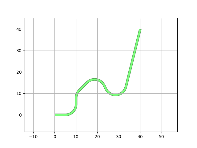
图4 输入几个关键坐标作为波导迹线生成波导结果图
2. 给定两个端口绘制波导
下面为一个例子:
from si_fab import all as pdk
from ipkiss3 import all as i3

wg_t = pdk.SiWireWaveguideTemplate()
input_port = i3.OpticalPort(name="in", position=(5.0, 0.0), angle_deg=0.0, trace_template=wg_t)
output_port = i3.OpticalPort(name="out", position=(50.0, 30.0), angle_deg=180.0, trace_template=wg_t)
route = i3.RouteManhattan(input_port=input_port,
                          output_port=output_port,
                          control_points=[(30,15)])
wg2 = i3.RoundedWaveguide(trace_template=wg_t)
wg2_l = wg2.Layout(shape=route)
wg2_l.visualize(annotate=True)
下图为运行结果:
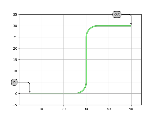
图5. 给定两个端口绘制波导结果图
如何将以上绘制的波导用在其他线路中呢?
from si_fab import all as pdk
from ipkiss3 import all as i3

class WAVEGUIDE(i3.Circuit):

     waveguide = i3.ChildCellProperty()

     def _default_waveguide(self):
         wg = i3.RoundedWaveguide(trace_template = pdk.SiWireWaveguideTemplate())
         wg.Layout(shape=[(0.0, 0.0), (10.0, 0), (10.0, 10.0),
                                      (20.0, 20.0), (30.0, 0.0), (40.0, 40.0)])
         return wg

     def _default_insts(self):
         return {
            "waveguide": self.waveguide,
         }

     def _default_exposed_ports(self):
         exposed_ports = {
             "waveguide:in": "in",
             "waveguide:out": "out",
         }
         return exposed_ports

if __name__ == "__main__":

     wg = WAVEGUIDE()
     wg_layout = wg.Layout()
     wg_layout.visualize(annotate=True)
这样在其他线路中只需要导入(import)WAVEGUIDE ,即可将其作为一个子器件进行线路的连接。
更多 Connector 函数的用法和例子欢迎查看我们的官方技术文档:


